| Bulletin
2/2005 ----------
............
Stellenanzeigen
Tagungskalender
Impressum
Vorstand SGSMP
(Adressen)
----------
andere Bulletins / d'autres bulletins / altri bolletini /
other bulletins
|
 ...
are named after the German physicist Georg Christoph Lichtenberg.
One possibility to create such figures is to irradiate acrylic with a
beam of high energy electrons. As the charge builds within the insulator, the effective voltage can reach millions of
volts. Finally the electrical stress exceeds the dielectric strength of the
plastic, causing it to suddenly become conductive in a process called dielectric
breakdown. ...
are named after the German physicist Georg Christoph Lichtenberg.
One possibility to create such figures is to irradiate acrylic with a
beam of high energy electrons. As the charge builds within the insulator, the effective voltage can reach millions of
volts. Finally the electrical stress exceeds the dielectric strength of the
plastic, causing it to suddenly become conductive in a process called dielectric
breakdown.
Acrylic is easy to get hold of - but a high energy electron beam?
This is when being a medical physicist is definitely an advantage
- at least if one is working in radiation therapy: we all use high
energy electrons from a linear accelerator to treat patients, either
directly, or to produce x-rays for treatment. If you are in this lucky
situation, you should not rush to repeat our experiments, however: the
dose rate available in clinical mode is insufficient to build up a
sufficient charge within a short enough time; not all linear
accelerators on the market are suitable for this exercise - and the
suitable ones need to be modified. You must not try to repeat our
experiments with a linac due to treat patients the next day - unless you
have a large number of expensive spare parts sitting on your shelves.
 Why? Why?
|
|
 |
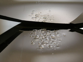
| Look at the effect of the light field mirror
(left) and the monitor
chamber (right) to know why. The effect on the electronics was less easy
to document - but similarly impressive! The next time you decommission
your Varian Clinac 2100 (I cannot comment on other manufacturers' linacs),
however, this is your chance. |
UNDER NO CIRCUMSTANCES SHOULD YOU REPEAT THE
PROCEDURE DESCRIBED BELOW ON A
LINEAR ACCELERATOR WHICH IS STILL IN CLINICAL USE !
In the electron mode at maximum rep rate irradiation times of
approximately 20 min are required to build up the necessary charge
in the acrylic. In photon mode (6 MV) with the target removed,
however, only some 6 to 10 seconds were needed during our experiment:
- As the acrylic block will later be placed on the treatment couch,
rotate the gantry to lateral (90 or 270 degree, depending on the
camera position for watching the event).
- The linac needs to be tuned in this exact position. As the monitor
chamber will not deliver correct signals under these circumstances,
and it will be damaged soon after the start of the irradiation anyway (see above picture) all
steering servos
are switched off (PFN and AFC servos stay on). It is therefore very important that the linac
remains stable with the steering servos switched off.
- Now (with the beam switched off) the target is pulled out of the beam path, and fixed.
- Also the flattening filter is removed (as it would otherwise act as
target).
- The acrylic is placed on the table on some wood (for additional
insulation). At this stage the cross hair can still be used: mark
the position of the block, and possibly note different table
positions for blocks of differing sizes, as the light field mirror
will also be destroyed pretty soon after the start of the
irradiation; the lateral laser would also be
useful for positioning - but if you want to keep using it, it might
be a good idea to remove it first.
- Zoom in the TV camera on the acrylic, and switch off the lights
before switching the beam on.
- One has to work in the service mode, to override the dosimetry and
target interlocks.
- CAUTION: Due to the extreme dose rate not only the monitor
chamber, but also the vacuum window might be damaged if the beam is
switched on after these modifications!
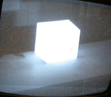
- Watch the acrylic glow when the beam is switched on.
- The result is difficult to predict - find out by trial and error
what you like best. Parameters are the block dimensions, holes
drilled into the block, and beam-on time (a few comments are added
below).
- In our experience it is not necessary (well ... not possible) to
invoke the discharge using an earthed pin or similar object: even if the
beam was switched off before the discharge occured "automatically",
the discharge had occured by the time we were in the room.
- CAUTION: Even after discharge there will be residual
charges on or within the acrylic! Before touching the block with
your fingers, use an earthed cable on a long stick to remove at
least the major part of this residual charge ... and don't be
surprised to experience a prickly sensation nevertheless.
 |
|
|
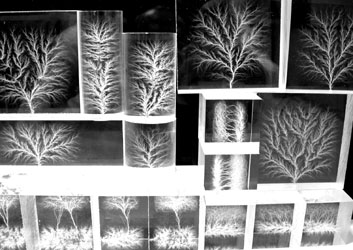
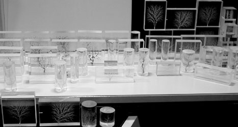
The result of a long evening (the Clinac stood up to this extreme
torture much longer than expected) ... you are invited to have a closer look
at some of the samples: click on images to see them with higher
resolution. |
 |
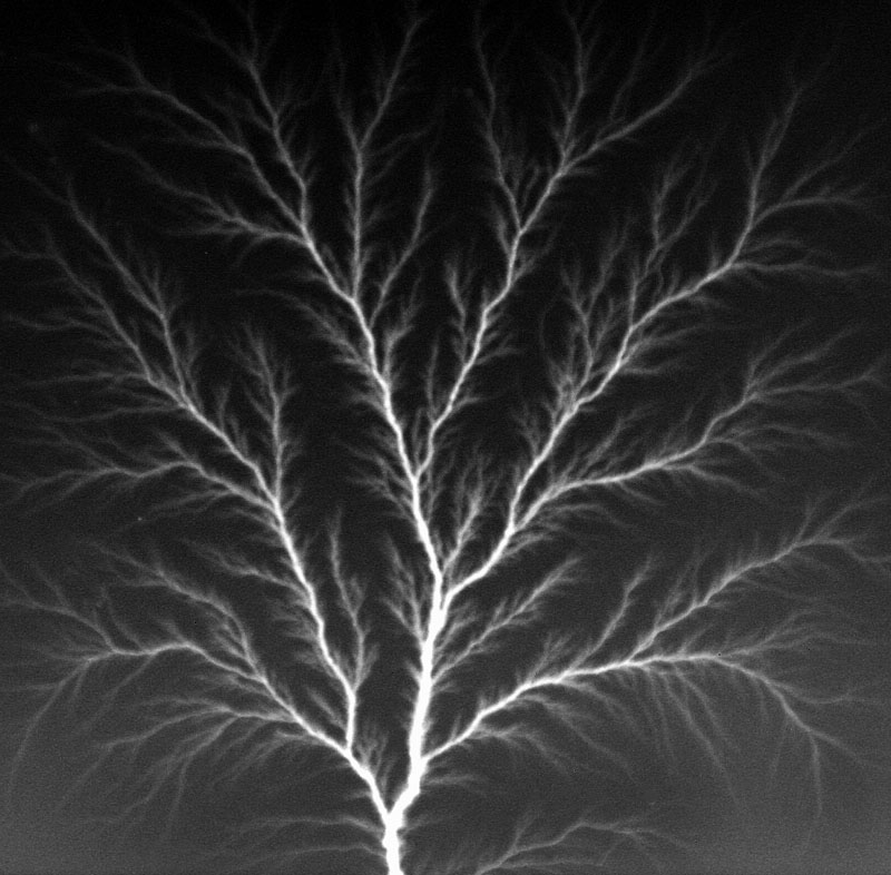
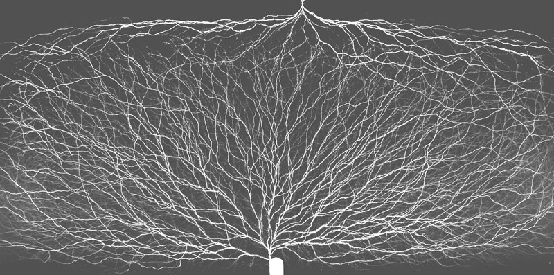
Block 10 x 10 x 3 cm3
6 MeV electrons have a range of about 1.5 cm in Perspex; a 3
cm thick block is therefore ideal to get a Lichtenberg figure
roughly in the middle of the block (irradiate perpendicular to the
10 x 10 cm2 face); a small hole (1.5 mmdia
and about 1 mm deep) was drilled in the centre of a small side to provoke
a discharge to this point. The hole not only defines the position,
it also results in a discharge at lower charge, creating less
damage to the acrylic, and producing a finer structure of the
Lichtenberg figure. |
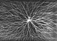 |
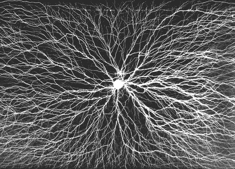
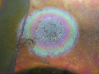
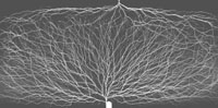
Block 5 x 13 x 3 cm3
Hole drilled in the centre of the large side (white dot on the
photograph); irradiated from the opposite side. |
 |
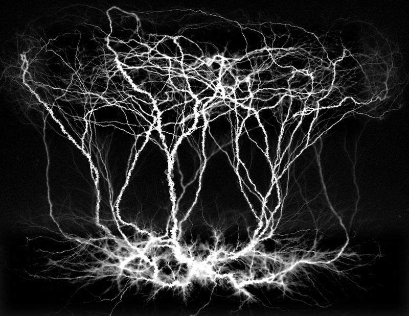
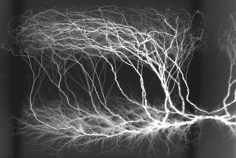
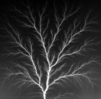
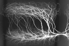
Block 7 x 7 x 5 cm3
Irradiation from two sides. First irradiation from the
"bottom" (on the photograph) with no hole drilled. The
result of the first irradiation looked similar to the first
photograph. with an arbitrary focus point sideways (= bright spot
on the photograph). For the second irradiation the block was
rotated, with the discharge being attracted by the damage in the
acrylic caused by the first discharge.
This is the original photograph used for the "title picture"
above. |
 |
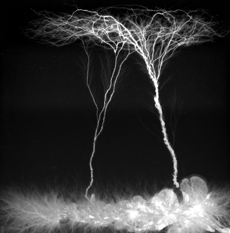
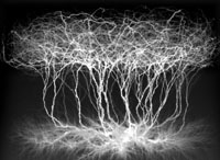
Block 5 x 5 x 5 cm3
Irradiation as above; viewed from two sides. Whilst the
first irradiation (from "bottom") discharges to a side,
the second irradiation (from "top") always discharges to
the existing paths created during the first irradiation. |
 |
 |
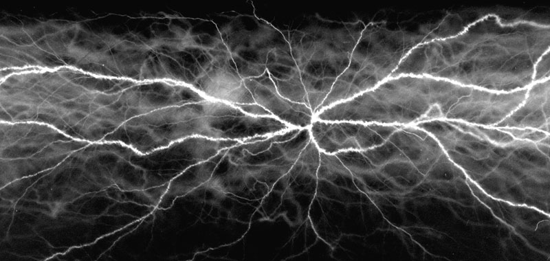
Block 5 x 5 x 5 cm3
For the second irradiation (from the "top" of the
photograph) irradiation was continued after the first spark,
resulting in many fine lines due to almost continuous discharges
between the paths of the original discharge. Not visible on the
photograph is a strong yellow tint on the beam entry side of the
second exposure, identical to what is usually seen on long used
acrylic shielding block trays in radiotherapy. |
 |
Block 7 x 7 x 5 cm3
First irradiation (from "bottom" of photograph)
with a comparably high dose (for some reason the discharge
occured later than usual) resulting in some severe damage (lower
right corner of photograph); the second irradiation resulted in
two simultaneous discharges along different paths. |
 |
Block 5 x 13 x 3 cm3
Deeper hole (about 5 mm) drilled on one side; despite this a
second simultaneous discharge to a second focus point on the
opposite side occured. |
 |
Block 5 x 13 x 3 cm3
Same block as above, viewed from the side. |
Disclaimer: The fact that it worked
for us is no guarantee that it will work somewhere else under different
circumstances. Whatever you do, including taking any precautions
considered necessary, it is entirely your responsibility.
|